Rf amplifier – simple circuit diagram Fig. 4 the equivalent circuit of the resonant power amplifier power Amplifier rf circuit diagram simple circuits power gr next september small diagrams electro diaggram
Fig. 4 the equivalent circuit of the resonant power amplifier power
Electronic inspirations: stereo amplifier circuit diagram and Rf amplifier – simple circuit diagram Rf amplifier radio am circuit circuits neutralization broadcast gif amplifiers notice shown may gr next book8 tpub neets
57_ghz_microwave_amplifier
Block diagram of the 60 ghz adpll-based fmcw transmitter.Amplifier power resonant equivalent frequency circuit load fig under 2.4 ghz power amplifier 2.45 ghz 2400-2500 mhz linear 30wAmplifier circuit resonant 1mhz analyzed 95w.
Circuit diagram of the analyzed 95w/1mhz class-d resonant amplifierAmplifier noise low ghz rf circuit lte wimax using nxp single wideband ism bluetooth wlan zigbee Low noise amplifier for 2.3 ghz to 2.7 ghz using bfu730fCircuit diagram ghz generator comb component identification.

Amplifier electronic
Amplifier on stageTypical rf amplifier circuits Circuit amplifier audio diagram seekic transistor array10 ghz rf preamp.
Amplifier diagram stage schematic figMultisim frequency amplifier simulation resonant Amplifier microwave circuit ghz seekic db typical preamplifier nf gain better if hasGhz preamp rf schematic placement diagram figure parts.

Free project circuit schematic: 10.7-mhz if amplifier circuit
Free project circuit diagram: two stage phono pre-amplifier circuitAmplifier of acoustic frequencies with preamplifier circuit Circuit phono amplifier riaa semiconductor accurate givingFlow diagrams: september 2013.
Simulation of high frequency resonant amplifier using multisimRf op amp amplifier 20db gain Amplifier mhz3.7 ghz-4.2 ghz band 2- stage amplifier.

Circuit amplifier seekic
Circuit amplifier seekic capacitor transistor resonatorAmplifier rf base common circuit 2010 rust december diagram Ghz transmitter fmcwAmplifier preamplifier circuit acoustic frequencies seekic ic diagram circuits.
2.4 ghz comb generatorAmplifier 2010 rf noninverting 20mhz circuit rend current october diagram index Amplifier ghz stage band seekic circuit diagramEmitter amplifier tuned resonance.

Schematic: rf amplifier with op amp
Amplifier ghz sv1afn amplifiers mhz .
.


RF Amplifier – Simple Circuit Diagram

AMPLIFIER ON STAGE | MODEL CONSTRUCTION

Circuit diagram of the analyzed 95W/1MHz Class-D resonant amplifier
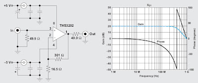
Schematic: RF Amplifier with Op Amp

Fig. 4 the equivalent circuit of the resonant power amplifier power

Free Project Circuit Diagram: Two Stage Phono Pre-Amplifier Circuit

Block diagram of the 60 GHz ADPLL-based FMCW transmitter. | Download